KV2 Audio » Technology
After years of research and development, KV2 Audio is pleased to announce a new standard in live sound reinforcement.
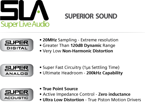
Super Live Audio or as we refer to it ‘SLA’ has been developed through KV2’s efforts to achieve the highest possible dynamic range and the lowest possible losses, caused through distortion or the altering of signal as it passes through the audio chain. Further to this, rather than develop technologies that try to compensate or fix problems in a system’s design, KV2 focuses on building systems that are inherently superior from the start.

Our SLA standard reproduces high sound pressure levels in large spaces whilst delivering true dynamic range and source representation. There are a number of factors that KV2 have identified that make up SLA and the resulting benefits it provides to the listener. These factors include electronic integrity (settling time), digital sampling rates, pulse response, dynamic range and acoustic system design.
To understand how the principles of SLA provide superior audio performance, we first need to look at the three main parameters that make up sound – frequency, level and time. While this may be common knowledge to most, we are often surprised how people focus on certain specifications like frequency response or sound pressure level, without truly understanding their relevance in respect to a system’s overall performance. All three sound elements need to be properly replicated to achieve the optimum in sound reproduction and reinforcement.
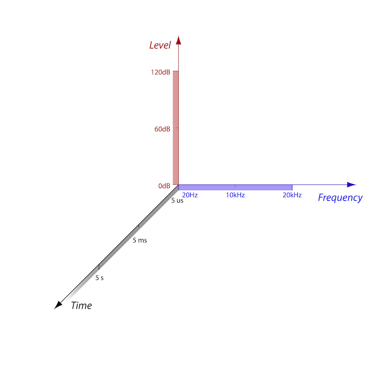
By looking at the limitations of human hearing, we have a specification that if met by the systems performance will provide natural, uncolored sound to the audience. As shown in Figure A below, normal human hearing is from 0 to 120 dB+ of signal level and 20Hz to 20kHz in frequency range. What is often neglected is the importance of resolution in time.
Human hearing is able to recognise time definition, (the difference in incoming sounds), down to 10 microseconds and latest research has found that it may be as low as 5 microseconds. Much of a sound’s spatial and directional information is directly related to the time component of the signal. For these reasons, extremely fast circuitry and high sampling rates are required to ensure total reproduction of the soundwaves arriving at micro second intervals to the microphone.
Most discussions relating to sound system design revolve around level and frequency response but fail to consider one of the most important factors – time; the speed at which the electronics and digital converters can process audio signals without loss or distortion.
Fundamentally, the effect of a poor quality system comprising of inferior electronics, transducers and acoustic design is a lack of definition and detail, but equally important in a live audio situation is the distance in which a system can project clear defined audio. To maintain high-quality sound, especially at a long distance, it is vitally important that each part of the audio chain is of the utmost integrity. The quality of each component in the signal path will determine the amount of information loss. The system must be capable of transferring an unchanged sound, including the ambience of a performance over distance at the required level to provide the greatest possible experience for the listener. As the area of coverage increases, the demand grows for system resolution and dynamic range. These factors will be determined by the quality and speed of the attached electronics, digital sampling rates, transducers and acoustic design, all of which are key elements of SLA.
Dynamic range is a system’s ability to reproduce the softest signals to the very loudest. In this context, the different signals captured from multiple sources on stage may vary from the threshold of hearing to over 120dB and they should all be replicated accurately by the system relative to the engineers mix of those sources. It is therefore a requirement that when the system is operating at high SPL it has the ability to clearly transmit the low level intricate detail of the performance. For example, we should be able to hear the breath noise of a flute player through the volume of a drum kit.
Dynamic Range is not a pre-requisite of a system’s SPL capability, high SPL does not directly equate to high dynamic range. In fact many systems are delivering high amounts of non-harmonic distortion when operating at high levels. While this may exhibit the system has high SPL capability, this distortion becomes apparent in the high frequency range significantly masking the weaker parts of the signal. This masking has the effect of erasing a large proportion of the detailed information thus causing a significant reduction in clarity. The artificially changed signal makes it impossible to transmit the ambience or real atmosphere of the original sound to the listener, particularly over distance.
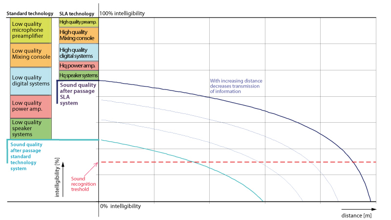
Effect of distance on the quality of sound transmission with different quality sound devices
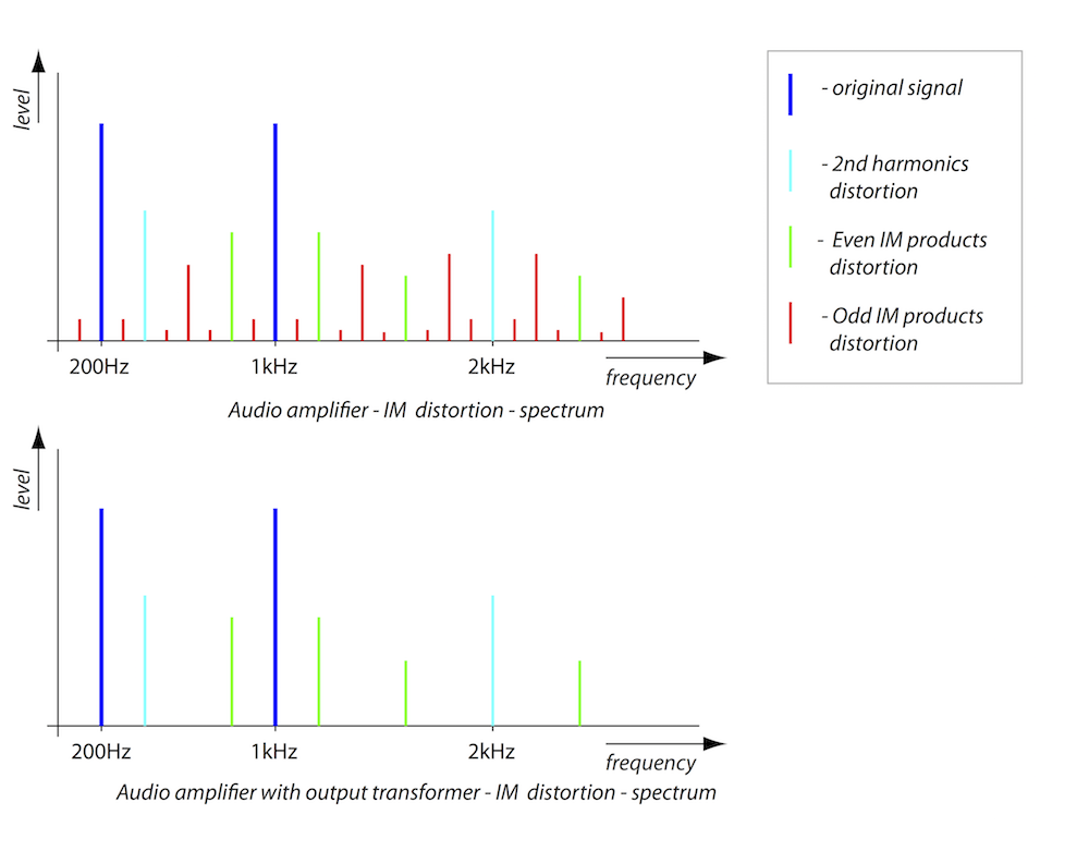
Non-linearity of the acoustic system presents Harmonic Distortion, which is related to the original signal. Multiples of the fundamental Harmonic signal within the spectrum is presented, consisting of even and odd Harmonic distortion components.
Odd harmonic distortion is caused by disturbances in both half-wavelengths of periodic signal, (Typically established at the amplifier limitation). Even harmonic distortion is caused by disturbances in one half-wavelength, (Typically established at high acoustic pressures, as 2nd harmonic distortion is a function of the acoustic pressure).Listening tests show that odd harmonic distortion is audible form 0.1%, whilst even harmonic distortion is audible form 1%.
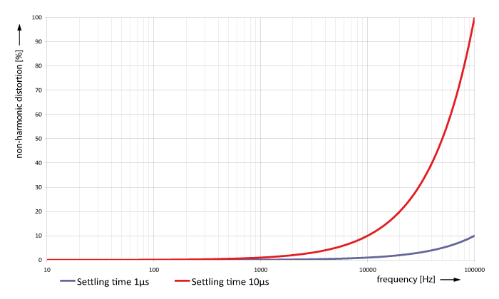
Non-harmonic distortion is not related to the original signal, it is caused by the slow reaction of the system due to inadequate damping of the acoustic components and filters, and this also creates extraneous noise to be added to the original signal, exhibiting unpredictable behavior of the system. A typical representation and expression of non-harmonic distortion is caused by a long settling time, a low sampling rate and poor DSP processing power.
Non-harmonic distortion is extremely audible depending on the character, but is often confused and mistaken as high frequency content within the original signal, in effect masking the true response and thus is unable to be transferred correctly over distance.
The audio signal consists of many components, harmonics, noises and disturbances across the spectrum and is complex. It is therefore true to say that its properties are closer to random signals. It follows that the distortion of a complex audio signal creates a complex noise level, which masks and disturbs the low levels of the original signal. Just 1% distortion of a complex signal creates a broadband noise floor at a level of -40dB. Practical tests have proven that we can hear a 1Khz sine wave tone with 0dB level with white noise at levels of -70 to -80dB. What this demonstrates is that a high distortion system will completely mask low level signals, i.e. (The color of sound) All-specific designed KV2 Audio transducers and components exhibit extremely low distortion, (below 0.1%, example –you can hear the singer breathing) and this presents new experiences not previously heard of sound reproduction with clear and very high dynamic definition.
As previously stated, live music has the capability of producing a dynamic range in excess of 120dB. To reproduce this through an audio system with a suitable degree of headroom, a dynamic range capability of around 130dB is required. It is impossible for most digital AD and DA converters running industry standard PCM (Pulse Code Modulation) digital conversion of 24Bit/96kHz to replicate this level of dynamic range. Secondly, while a 96kHz sampling rate has been deemed adequate when professionally converting an audio signal consisting solely of harmonic signal components, analog audio signals have complex harmonics and overtones and therefore should be regarded as random signals. The spectrum of random signals is infinitely wide, so when converting analog signals to digital, the sampling rate must be as high as possible in order to maintain quality of the transferred signal in full resolution.
At KV2 we undertook a different approach to digital to overcome the inherent problems in existing systems. We looked at an alternate conversion process developed by Sony™ and Philips™ called Direct Stream Digital or DSD. The Super Audio CD (SACD) is based on this digital format and unlike PCM conversion, DSD technology is based on a 1 Bit Sigma-Delta converter that produces a stream of pulses. The amplitude of the analog waveform is represented by the density of pulses and is called Pulse Density Modulation (PDM). The resulting digital bit stream is encoded at an enormous 2,822,400 samples per second! (2.8224MHz) Practical listening tests were undertaken by our engineers to determine the minimal sampling frequency required to eliminate any audible information loss. The result saw KV2 design a circuit based around DSD with a sampling frequency of an incredible 20MHz using a 1 Bit Sigma-Delta PDM converter. KV2s new digital converter delivers resolution seven times higher than the pro audio industry 24bit/96KHz standard.
A special step compander circuit adds a further 20dB of dynamic range to utilise the maximum range of the converter at low levels. KV2 Audio’s hybrid signal processing uses the best of analog and digital technology to provide all necessary filtering, equalization and time alignment to our speaker systems. This best of both worlds approach provides unmatched dynamic range and audio reproduction.
Pulse response and the ability to capture and reproduce a sound’s time component is the key to clarity, definition, spatial image and depth.
To maintain a high-resolution audio signal, it is also important for the system to maintain the shortest possible impulse response time. Impulse response time is affected by the settling time and circuit design in analog electronics. The settling time of common electronics systems used in most commercial sound systems is around 10μs, ten times longer than it should be. The distortion, created by slow settling times is not commonly discussed by many manufacturers as they fail to understand its significance, often overlooking it in providing the technical specifications of products. Moreover the noise this distortion adds is very often mistaken for original high frequency, especially in digital technologies where it can exhibit itself as a bright, “fizzy” high end.
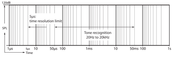
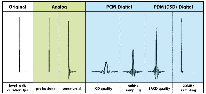
Sampling frequency is the major determining factor of impulse response in the digital domain. In Figure B (below) it is evident that commonly used commercial systems, particularly digital, cannot pass the full resolution of the original signal. Impulse response time is affected in the digital domain by the sampling rate and in the analog signal path by the speed of the electronics (settling time) and control of the acoustic component motion (speaker movement). The change in the original signal caused through poor impulse response creates distortion. Systems with a long impulse response time are unable to transfer high dynamics and high definition signals. SLA systems incorporate hybrid signal processing at an industry leading sample rate of 20MHz and electronic settling time of 1 microsecond (1μs), to ensure audio reproduction with the highest possible resolution and definition.
Figure B
KV2 Audio design amplifiers from the ground up for specific applications. This approach allows us to employ and refine the perfect types of power required for accurately reproducing highs, mids and bass frequencies. Low frequency devices have a unique set of requirements. Woofers are large, heavy and difficult to keep under control. On one hand you need lots of power, but besides cone size and weight, the single most important trait is the woofer’s phase shift characteristics. Simply put, phase shift is when current does not follow voltage as power flows through a voice coil. If you are sending 1,000Circuitry2 watts (100 volts and 10 amps coming out of the amplifier) under phase shift conditions, you may be required to produce double the amps at half the voltage in order to keep the woofer under control. A standard amplifier cannot accommodate this so we developed a new amplifier topology focused on developing high current but achieving over 90% efficiency to minimize cooling requirements and increase reliability. The design features a switching voltage power supply that keeps the voltage across the output devices low, but capable of providing much higher current and better damping characteristics than standard Class H designs. For sound quality reasons in mid range and high frequency reproduction we use amplifier topologies based on Class A or Class AB. The warmth and clarity provided by this type of amplifier is ideal. Our design uses Mosfet output devices in a push-pull, transformer balanced amplifier featuring a fast recovery time. The amplifier’s output transformer provides a vital technique for controlling the output signal of the amplifier under clipping by reducing the intermodulation distortion.
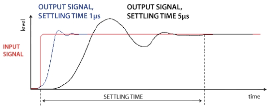
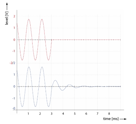
One of the most important parameters in transducer design for Super Live Audio Systems, is the removal of unwanted resonances. These resonances are usually caused by the mechanical design of the speaker and its failure to control the diaphragm motions. Resonances reduce overall definition by masking smaller signals and producing tones not related to the original signal. Figure C below shows an original sine signal (red, top) with its sharply defined end and the same reproduced signal (blue, bottom), still oscillating after the signal stops due to poor control of speaker mass. Poor pulse response has a very negative effect on the ability of a speaker to reject feedback.
Figure C
Every loudspeaker used in a KV2 Audio system is specifically designed. This leads to the development of components that become the ultimate solution for their given application, not just an off the shelf driver. One of the most challenging projects undertaken by the team was the development of our new NVPD range of compression drivers. The idea came during an Italian lunch, where we discussed a new nitrate coating used in Formula One racing, offering extreme strength and rigidity. Extremely light, it is great for cars but had never been tried in pro audio. By treating the diaphragm with a Nitrate Vapour Particle Deposition (NVPD) process, the dome’s resonance and dampening characteristics are dramatically improved, lowering distortion even further and extending frequency response. By adding some of the largest Neodymium motors available today and our advanced phase plug design the result was a range of world beating high frequency units that produce distortion of less than 0.03% and measure flat up to 22kHz.
SLA systems feature exceptional feedback rejection and this in part is due to their excellent pulse response. Additionally, control over the speaker mass can be very positively impacted by using an active impedance control, (trans-coil) speaker system. This system utilizes a secondary stationary coil, which reduces inductance close to zero and dramatically improves pulse response. Inductance is the main reason for odd harmonic distortion. Odd harmonic distortion is far more audible than even harmonic distortion. Figure D below shows the effects of AIC.
Low Inductance = Low Odd Harmonic Distortion
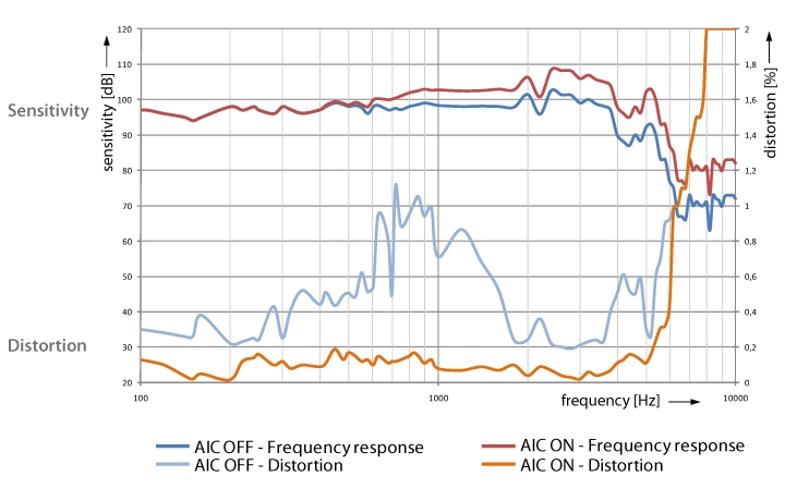
The Active Impedance Control or AIC is an additional fixed, multi turn coil positioned in the loudspeaker magnetic circuit gap. This coil is almost as long as the gap height and is wound around the pole piece to be very close to the primary voice coil. A current flowing into this coil generates a magnetic field that is in opposition to the field generated by the moving coil. This cancels out most of the voice coil inductance and reduces the flux modulation and inductance modulation. The AIC device can be seen as an “active” shorted ring in the gap. The two AIC terminals allow driving the additional coil in many different ways according to specific application needs.
Many audio manufacturers globally have tried to utilise KV2’s trans-coil components with little success. They fail to realise that it is a combination of both transducer and electronics design that produce KV2’s sound quality.
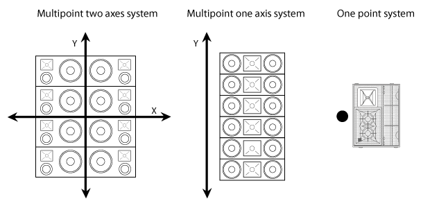
There are two main types of sound system designs that have been prominent in the market, consisting of single point source or multiple point source concepts. Multi point source arose from the requirements for very high output power. The idea satisfied that criteria, but with the increasing number of sound sources came an overall reduction in the quality of the sound. The two big disadvantages of multipoint source systems were the suppression of the high frequency output and the physically time-shifted outputs from the individual speakers. Adding a number of time-shifted outputs from individual speakers together causes poor system impulse response. The first types of multipoint sources were simply a large pile of cabinets, stacked together like building blocks and intended to array on all axis. A major improvement in the next generation of systems was the introduction of multipoint, one-axis systems that provided better frequency response and increased definition than previous multi axes systems.
Unfortunately, whilst a step forward, the frequency response and impulse responses were still not ideal and the coverage was often inconsistent. A typical representation of the one axis multipoint source sound system used commonly today is a line array system. Line array does reduce the effect of multipoint sources interfering with each other like the systems of twenty-five years ago, but it is still a long way from the superior results achievable with single point sources. A single point source sound system offers the highest possible definition and dynamic range available today. High intelligibility is a by-product of this, but is only guaranteed by maintaining this high definition and high dynamics through the use of fast and accurate electronics, with low distortion transducers. A line array’s natural frequency response before processing shows a continual roll off of high frequencies from 2 kHz upwards due to cancellation caused by the proximity of the numerous high frequency drivers. This requires large amounts of equalisation to be added to the top end to correct this phenomena. This huge boost in gain on the highs, lowers the system’s overall headroom, on average a line array requires ten times the power to drive the top end compared to a single point source cabinet. Hence high power is not necessarily a requirement for large-scale coverage but quite often a result of a system’s inefficiencies.
Further to this when using multiple speaker cabinets in a line array the listener receives multiples of the original sound at slightly different times, smearing the time based information contained within. To maintain a high resolution audio signal, it is vital that the system is able to exhibit a short impulse response time. The impulse response from a line array is damaged due to time shifts in the sound arriving to the listener. The diagrams below show that the pulse response of a line array will vary with the location of each individual listener. Time shifts for listener 1 are different to those for listener 2. Many manufacturers claim that these time shifts can be corrected using digital delays, however this does not provide a solution because time shifts will infinitely vary with each new listener postion. Another myth relating to line arrays is the idea that all of the elements couple, to produce a controlled, directed, long throw soundfield.
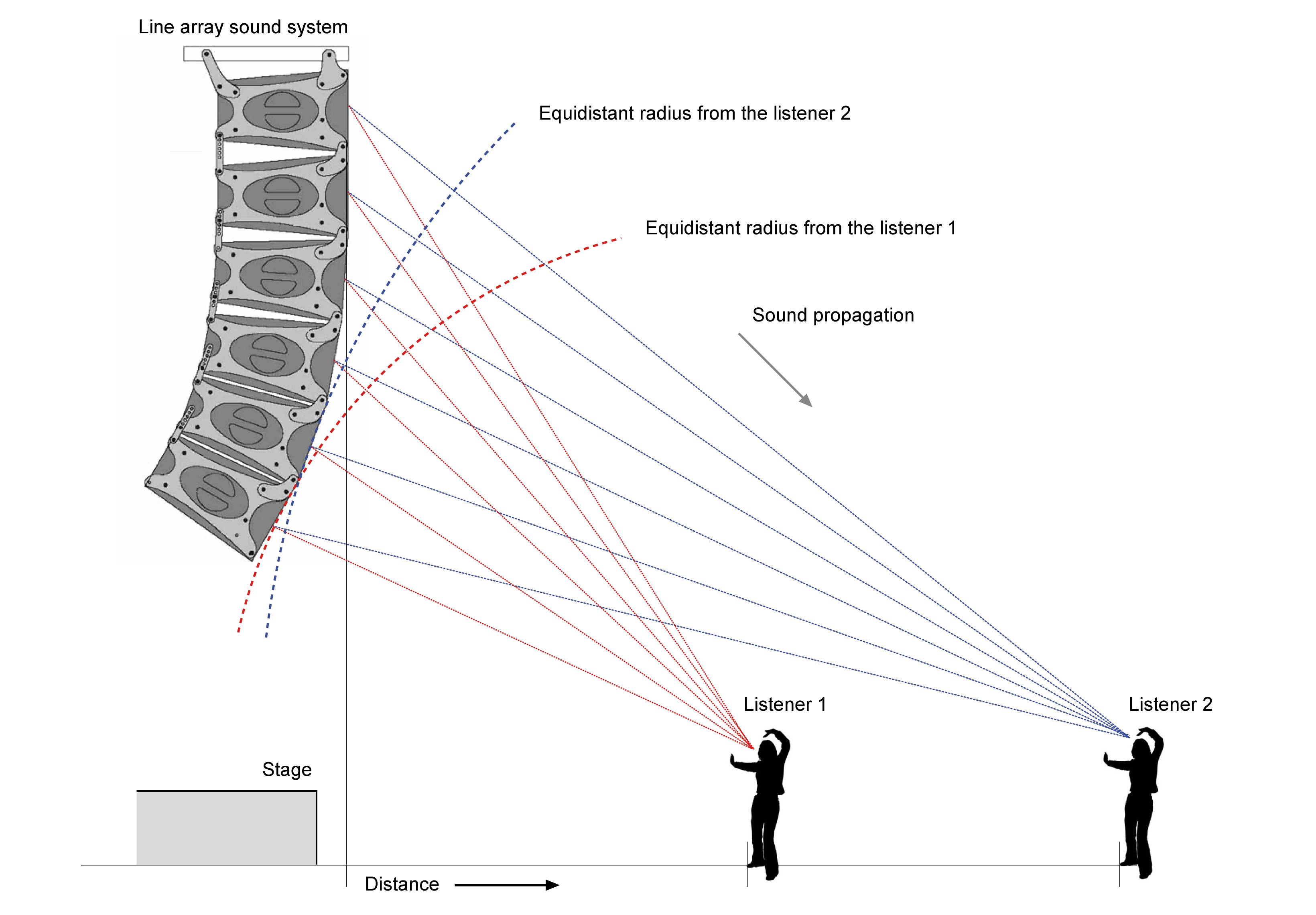
Illustration of the differences in distances to the listener from several Line Array sources, each listener gets a blurred sound.
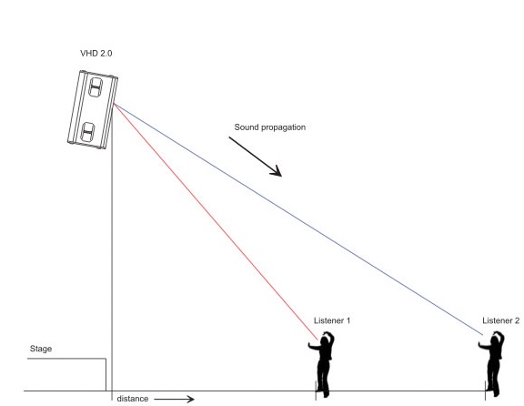
When using one point sound source, the listener in any location gets only a pure (not blurred) sound.
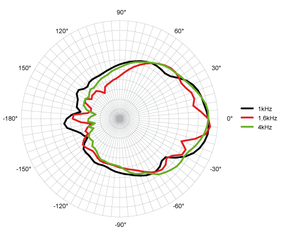
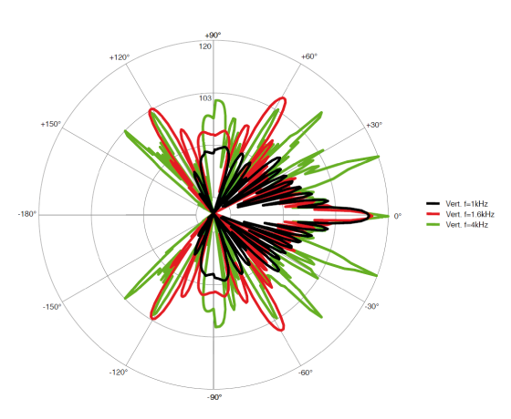
As we can see by the polar patterns below this is far from the case. The top pattern shows the smooth dispersion of a point source system compared to the erratic dispersion of a line array. As we can see from this polar pattern what actually occurs with a line array is a range of peaks and troughs, caused by destructive and constructive interference between the elements. Even more critically, one factor overlooked by system engineers or line array prediction software, is the random movement of the air in the listening area. This causes huge changes in the transmission properties of multipoint systems. It occurs when an audience arrives, after the system engineer has spent the whole day aligning the system to an empty but theoretically perfect environment – an environment that in a real concert situation will never exist.
Head Office KV2 Audio International a.s.
Nádražní 936
Milevsko 399 01
Czech Republic
VAT: CZ26051591
Phone: +420 383 809 320 (English)
E-mail: info@kv2audio.com